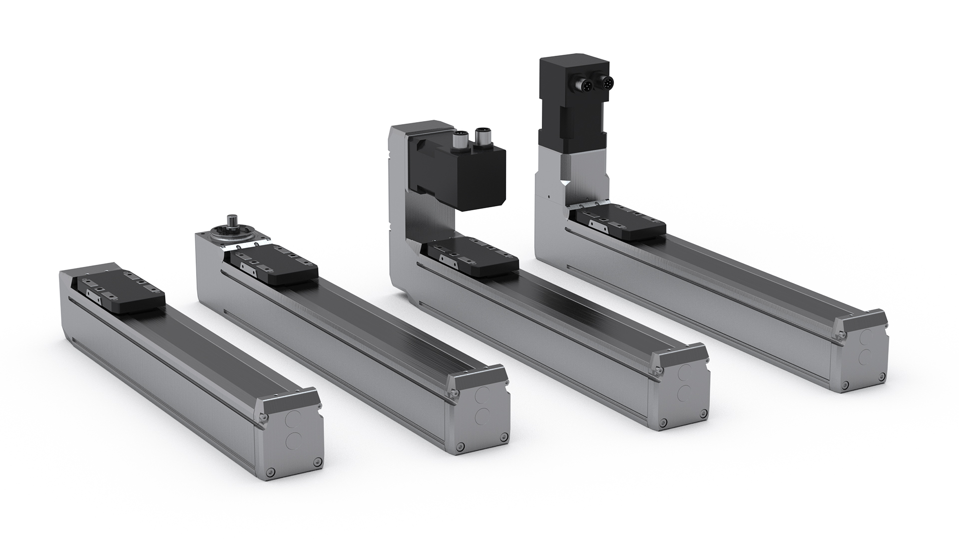
MINI LINEAR UNITS MGBS & MGTB
MGBS & MGTB are modular and cost-effective rod-less electromechanical linear drive units. They feature a high capacity and high precision linear guide system with either a precision ball screw (MGBS) or a timing belt transmission (MGTB) to convert a rotary input to linear motion and force. The position repeatability ranges from ± 0.015 mm to ± 0.08 mm.
Endurance
Our range of miniature units is designed to survive in the most intense automation situations, counting several million cycles over its lifetime. And this with practically no need for maintenance. High-quality components are used from inside and out, starting with a robust anodized aluminium extrusion as the base. Inside only first-rate bearings and ball screws are used.
Sustainability
Our miniature linear units have highly efficient mechanical solutions, and the size and form factor to easily replace a lot of functions traditionally driven by pneumatics. The faster and more frequent the motion is, the greater the potential energy saving. On a system level, pneumatic motion has a typical efficiency between 5 to 10 %. Electromechanical systems with low friction mechanics easily achieve over 50 % system efficiency.
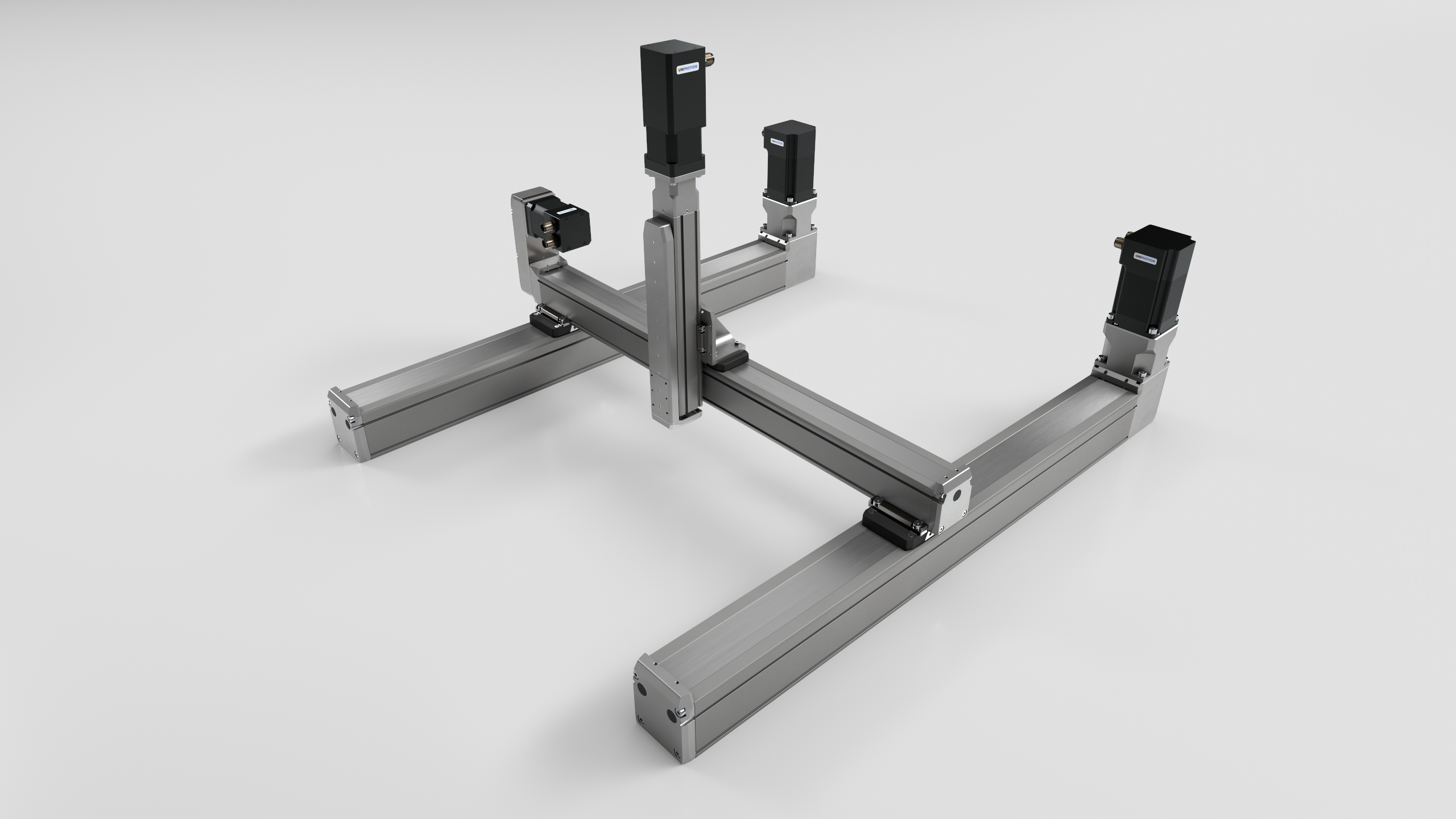
Modularity
The MG series is a further extension of the MCE and MSCE miniature cylinder series, sharing the same outer shape and mounting hardware. The motor interfaces, in-line with a coupling or parallel over a belt drive, are the same for both MG and MCE/MSCE. To enable the best value and shortest delivery time, MG is batch produced and stocked in several standard stroke lengths.
Proven system performance with our stepper motor system
All our miniature drive units can be calculated and mechanically adapted for your preferred motor, given it is within suitable physical dimensions. But to save time and cost, our stepper motor system is an excellent choice. The performance of all combinations of linear miniature units and our motors is already calculated and validated.
Why stepper motors?
For small drives, up to 100 W of mechanical power, a stepper motor system excels through its simplicity, power density and low cost compared to a synchronous EC-motor, for many known as a “brushless servo motor”. The savings are on all parts of the system, including the motor, the cables, and the drive electronics but also on the cost and time spent on commissioning and tuning the system. A stepper system does not require any tuning of motor parameters.
The common downsides of a stepper system, such as noise and the risk of stalling and losing its position, are compensated by a standard offering on all our stepper systems with a 2000 counts per revolution encoder and with a drive that makes it a closed loop system. The drive electronics also work with micro-steps, up to 10 000 steps per revolution. This reduces audible noise emissions significantly.
Drives
The stepper motor drives are more than just a power stage to drive the motor. They are all low-voltage drives, running on 24 or 48 VDC. They facilitate closed-loop operation by reading the motor encoder. A dynamic lag error of up to half a motor turn lasting up to 1 second can be handled and recovered, giving a very robust and reliable drive even if external mechanical loads on the system fluctuate. Special drive modes, such as simple load sensing, can emulate the function of “torque mode” of servo motors and enable “push to mechanical stop” functionality. A very typical use case for pneumatics that normally is not that straight ahead to implement in an electromechanical drive system.
The drives are available with four different external communication interfaces. The basic version is the classical Pulse + Direction, where a dedicated positioning system producing a pulse train is required. For multi-axis applications, three different field busses are available, namely EtherCat, Ethernet-based communication and ProfiNet. In addition to the bus interfaces, there is a set of digital I/O for some dedicated use such as end limit switches and brake control but also some freely programmable. Together with an in-the-drive stored position register, limited stand-alone functions can be realized too.
READ MORE ABOUT LINEAR UNITS ON OUR BLOG ![]()
![]()